En:ElectriX
| Language EN [[{{#sub:En:ElectriX|3|{{#len:En:ElectriX}}}}|SK]] | Navigation: | Projects -> Measuring components -> ElectriX |
| Name | ElectriX |
| Version | 1 (junior) |
| Description | Educational application for calculating the parameters of simple electrical circuits. |
| Used libraries | Library info.kiwiki.measurelib |
| Icon | 
|
| Compatiblity | Minimal OS Android version: 2.2 - FroYo (API 8) |
| Optimized for | Tablets, cell phones with 3" and more display size |
| Language | Slovak, English (EN, SK) |
| Download |  
|
| Author | Juraj Ďuďák (Redaktor:Juraj) |
Obsah
Properties
- The application simulates a simple electric circuits.
- Presented examples demostrates the apllication od Kirhoffs laws.
- In hhe current version are available these circuits:
- Electrical resistance - Calculation of final resistance for series and parallel resistor connection
- Simple circuit - demonstration of Ohm Law
- The voltage divider - electrical circuit with 2 resistors connected in series
- Complex circuit - a circuit with a 2 loops
- The voltege divider with load - demonstration of the impact load resistor in voltage divider
- First Kirhoffov Law - electrical circuit with 3 resistors, which are connected in parallel
Main screen of ElecriX
Control
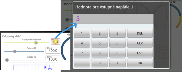
Changing the parameters of prepared circuits going through the labeled sliders. When change ismade, entire circuit is immediately recalculated with new values. Result values are also immediatelly displayed on the appropriate measuring device. To enter exact values is the ability to use software numeric keypad, which is invoked by clicking/tapping to the part where you see the value. This procedure is outlined in the following figure.
Analysis of electric circuits solutions
Electrical resistance
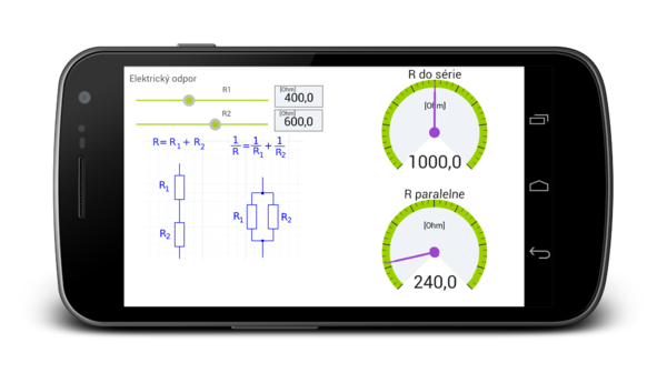
Sample calculation of the resulting electrical resistance of two resistors connected in series and in parallel.
Used relations
- Serial connection: [math]R = R_1 + R_2[/math]
- parallel connection: [math]\frac{1}{R}=\frac{1}{R_1}+\frac{1}{R_2}, R=\frac{R_1R_2}{R_1+R_2}[/math]
Screenshot
A simple electrical circuit
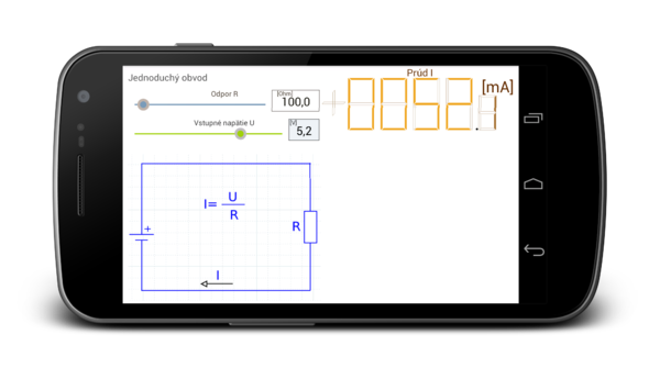
Sample calculation of the resulting electrical resistance of two resistors connected in series and in parallel.
Used relations
- For this engagement apply Ohm's Law: U=R*I
- To calculate the electric current: I=U/R
Screenshot
Voltage divider
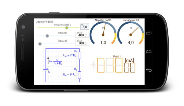
A simple circuit with 2 resistors connected in series. At each resistor is voltage drop proportional to the cross-ratio values of resistors. The sum of these voltage drops is equal to the supply voltage U.
Used relations
- For this engagement apply Ohm's Law: U = I * R, where R is the total resistance of the resistors R1 + R2; therefore applies: U=(R1+R2)*I
- The voltage drop across the resistance:
- [math]U(R_1)=I*R_1[/math]
- [math]U(R_2)=I*R_2[/math]
Screenshot
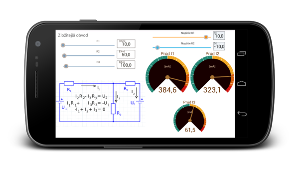
Complex circuit
Electrical circuit with two loops. To solve this circuit are used first and second Kirhoffov law [1].
Used relations
Denote the direction of the electric current, as shown below.
For the first loop equation is valid: [math]-U_1 + I_1R_1+ I_3R_3 = 0[/math]. Pre druhú slučku: [math]U_2+I_2R_2-I_3R_3 = 0[/math]. Pre prúdy platí: [math]I_1-I_2-I_3=0[/math]
We can rewrite the equation as follows:
[math] \begin{matrix} I_1R_1 & & +I_3R_3 & =U_1\\ & I_2R_2 & -I_3R_3 & =U_2\\ I_1 & -I_2 & -I_3 & = 0 \end{matrix} [/math]
In matrix form equations have the form:
[math] \begin{pmatrix} R_1 & 0 & R_3\\ 0 & R_2 & -R_3\\ 1 & -1 & -1 \end{pmatrix}\cdot \begin{pmatrix} I_1\\ I_2\\ I_3 \end{pmatrix} = \begin{pmatrix} U_1\\ -U_2\\ 0 \end{pmatrix} [/math]
This system of equations can be rewritten symbolically as:
[math]\mathbf{R}\cdot \mathbf{I}=\mathbf{U}[/math]
then the solution is:
[math]\mathbf{I}=\mathbf{R^{-1}}\cdot \mathbf{U}[/math]
where [math]\mathbf{R^{-1}}[/math] is the inverse matrix. How to calculate the inverse matrix is well known [2][3]. The resulting inverse matrix [math]\mathbf{R^{-1}}[/math] has value:
[math] \mathbf{R^{-1}}=\begin{pmatrix} -R_2+R_3& -R_3&-R_2R_3 \\ -R_3 & -R_1-R_3 & R_1R_3\\ -R_2 & R_1 & R_1R_2 \end{pmatrix}\cdot \frac{1}{D} [/math]
Where D is the determinant of matrix:
[math]D = -(R_1*R_2 + R_2*R_3 + R_1*R_3)[/math]
The solution of the equation is:
[math] \mathbf{I}=\mathbf{R^{-1}}\cdot \mathbf{U} = \frac{1}{D} \begin{pmatrix} -R_2-R_3 & -R_3 & -R_2R_3\\ -R_3 & -R_1-R_3 & R_1R_3\\ -R_2 & R_1 & R_1R_2 \end{pmatrix} \cdot \begin{pmatrix} U_1\\ -U_2\\ 0 \end{pmatrix} = \frac{1}{D} \begin{pmatrix} -U_1(R_2+R_3) + U_2R_3\\ -U_1R_3 - U_2(R_1+R_3)\\ -U_1R_2-U_2R_1 \end{pmatrix} [/math]
The final expression of the solution:
[math]I_1 = \frac{-U_1(R_3-R_2) + U_2R_3}{D}[/math]
[math]I_2 = \frac{-U_1R_3 + U_2(R_1+R_3) }{D}[/math]
[math]I_3 = \frac{-U_1R_2 + U_2R_1}{D}[/math]
Screenshot
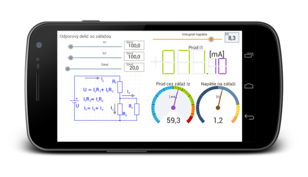
The voltage divider with load
This example is just a special case of the previous example. The difference is that in the other half is not connected power voltage. In this example, we are interested in the voltage drop across the load (resistance R) and current to the load (Iz).
Used relations
The system of equations for this example:
[math] \begin{pmatrix} R_1 & R_2 & 0\\ 0 & R_2 & -R_z\\ 1 & -1 & -1 \end{pmatrix} \cdot \begin{pmatrix} I_1\\ I_2\\ I_z \end{pmatrix}= \begin{pmatrix} U\\ 0\\ 0 \end{pmatrix} [/math]
Inverse matrix R ^ (-1) is:
[math] \mathbf{R^{-1}}= \begin{pmatrix} R_2+R_z & X & X\\ R_z & X & X\\ R_z & X & X \end{pmatrix} [/math]
X are matrix elements that do not need to count, because the right side of the vector equation has the second and third row of zeros. The resulting currents have values:
[math]I_1= \frac{U(R_2+Rz)}{D}[/math]
[math]I_2= \frac{URz}{D}[/math]
[math]I_z= \frac{UR_2}{D}[/math]
where D is the determinant of a matrix R is equal to:
[math]D=R_1R_2 + R_2R_z + R_1R_z[/math]
Screenshot
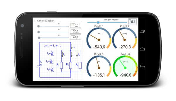
First Kirhoffov law
The following example illustrates the use of first Kirhoff law. In circuit are three resistors connected in parallel, so the voltage drop across the resistor is the same. They differ only value streams that flow through the branch circuit.
Used relations
Voltage drop across the resistor is the same as the value of the supply voltage U. For individual streams relations apply:
- [math]I_1 = \frac{U}{R_1}[/math]
- [math]I_2 = \frac{U}{R_2}[/math]
- [math]I_3 = \frac{U}{R_3}[/math]
- The total current is equal [math]I = I_1+I_2+I_3[/math]
Screenshot

